
About Clarifier Mechanism
Primary Clarifier
Primary Clarifier: The flocculated effluent will enter into the circular primary clarifier made of RCC construction through centre feed pipe. The clarifier has circular geometry and has drive mechanism, access platform, rake arm mechanism mounted on it. From the centre feed pipe, effluent will entered into the settling zone of clarifier. The clarifier will be designed based on the settling velocity particle. In settling zone, flocculated particle will be settled down and formed sludge at the bottom of clarifier. The clarifier will have two scrapper rake arms settled sludge. The settled sludge shall be transferred into the sludge holding tank by gravity. The clarified water will rise at the top of clarifier and will be collected into the outlet weir. From the weir it will be collected into the clarified water storage tank by gravity.
Secondary Clarifier
The function of the secondary clarifier is to separate the activated sludge solids from the mixed liquor that is generated in Aeration tank. These solids represent the colloidal and dissolved solids that were originally present in the wastewater. In the aeration unit they were incorporated into the activated sludge floc, which are settleable solids. The separation of these solids, a critical step in the activated sludge process, is accomplished in the secondary clarifier. The excess sludge production from secondary clarifier is pumped to sludge holding tank by a tapping from RAS pump. The purpose of return sludge is to maintain MLSS concentration of activated sludge in the aeration tank sufficient for the desired degree of treatment.
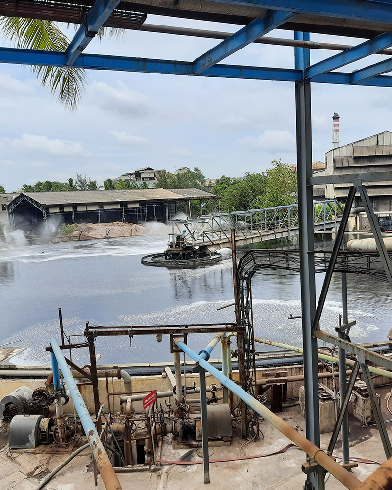
High Rate Solid Contact Clarifier
HIGH RATE SOLID CONTACT CLARIFICATION (HRSCC) Water clarification is the process of removing suspended solids, turbidity, colloids from water. The HRSCC has been designed such that coagulation, flocculation, setting and sludge remove are combined in a single tank. HRSCC are designed to treat different type of water for a various application for solid settling and separation. These units are tailor - made to suit various flow rates and can design for very large flows. For optimum operation effective solid separation HRSCC employs use of flash mixer, and stilling chamber prior to clarifier. Typically chemical treatment using Alum, Zinc and polyelectrolyte are used to aid coagulation &flocculation and enhance removal of solids.
HRSCC comprises of the following:
There are two drives in the HRSCC: one drives the sludge disposal rake and the other drives the turbine mixer which re circulates the sludge. Coagulation, flocculation, setting and sludge removal is combined into a single tank. Concentrated solids, which have earlier settled in the clarifier, are recirculated to the mixing zone by the turbine and mixes with the incoming influent which has a relatively low concentration of suspended solids. The rate of flocculation is directly dependent on the solids concentration (by volume). Therefore by recirculating the settled floe, the amount of solids increases, thereby improving flocculation and hence the name Solids Contact Clarifier. This also results in lower requirement of coagulation chemicals since contact of this floc which has been formed earlier with new floc results in good growth of the same. This water then flows into the reaction well where the solids coagulate and settle. The flow passes through the sludge blanket at the bottom of the reaction well and this further removes suspended particles. The rotating rake arm moves the settled solids or sludge to the center of the clarifier for r emoval. The flow rises upward in the clarification zone and water is removed by the redial collection troughs on the surface. A portion of the settled sludge is periodically drawn off by opening the blow down valve. The recirculation of sludge result in the HRSCC producing water of very low turbidity for a wide range of inlet suspended solids level and even in conditions of low inlet turbidity.
Salient Features
Application
Note
Precision Engineering Company,
Plot No.3, Ezhil Nagar, Otteri, Vandalur, Chennai - 600048 Phone
+919940488539
+917010889294
Email: info@precisionengineer.inPopular Services
Goods and Service Tax
Quick Links
Design and Developed by Deshva Pvt Ltd.,